2024-Current Toyota Land Cruiser Front Hybrid Bumper Installation Guide

A black and red metal skateboard wheel support bracket

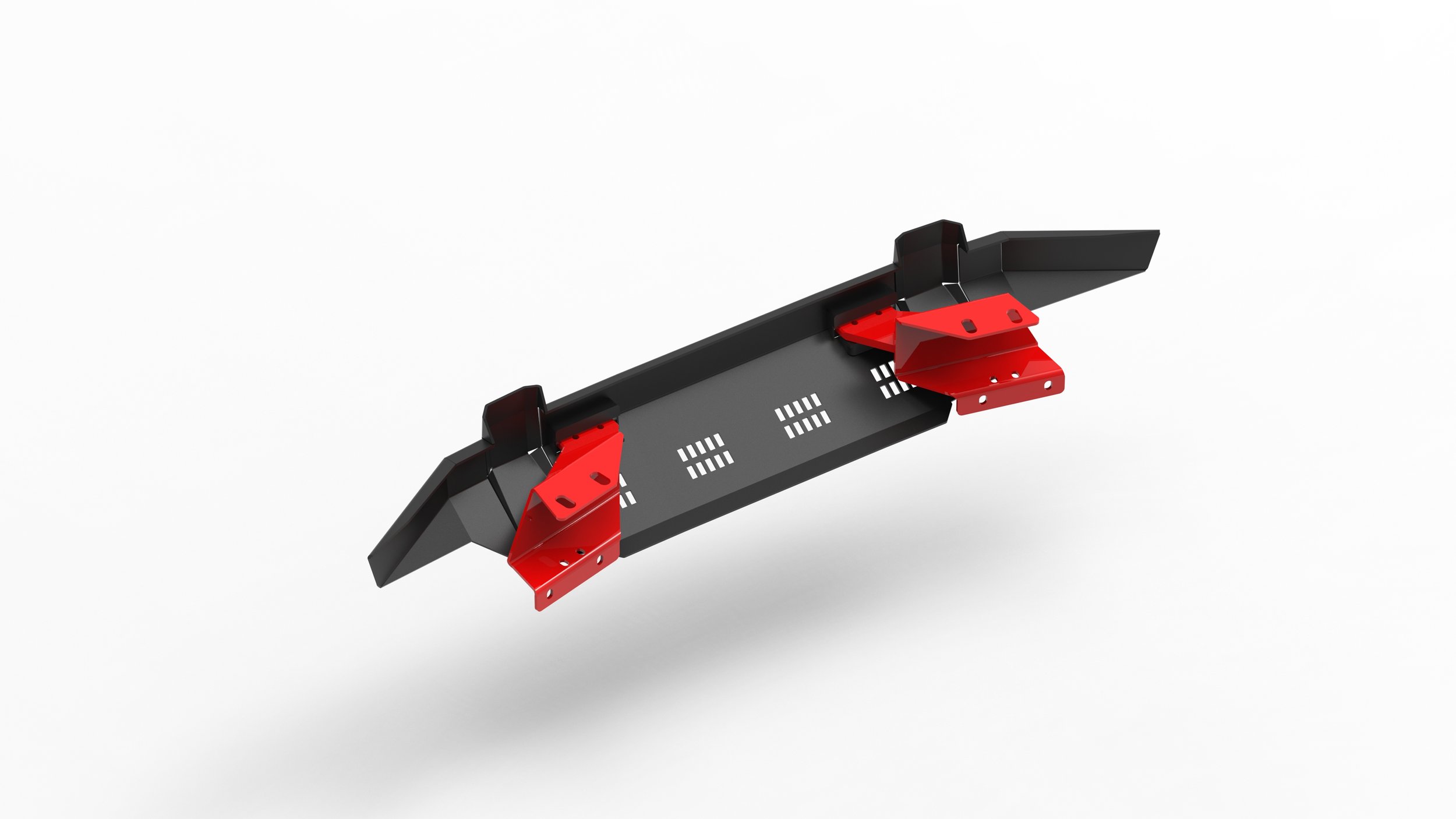
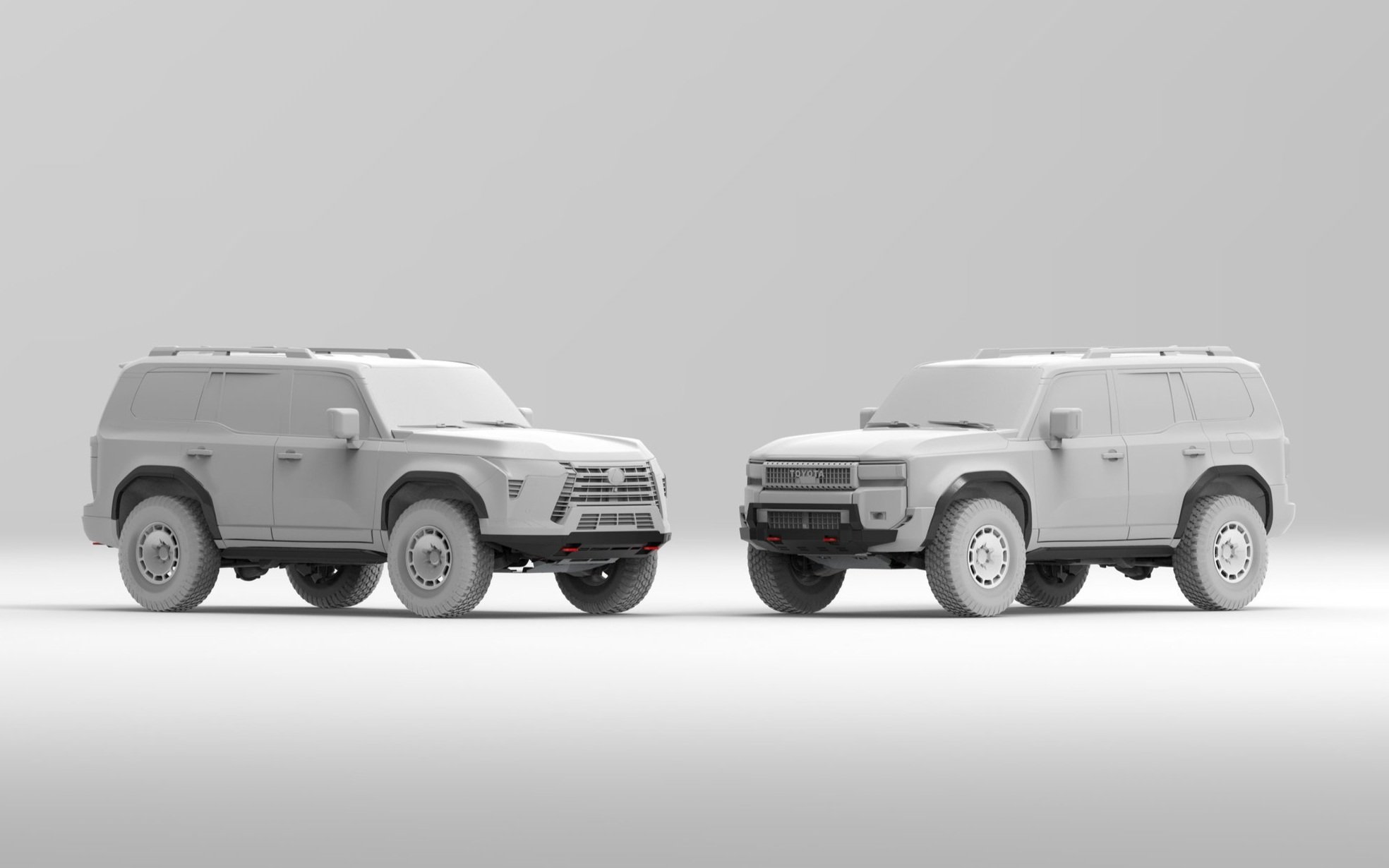
A quick preview of the bumper assembly.

Under the vehicle, three circular holes in a black panel, with red arrows pointing to them.
Close-up of the interior of a machine with three bolts circled in red for reference.

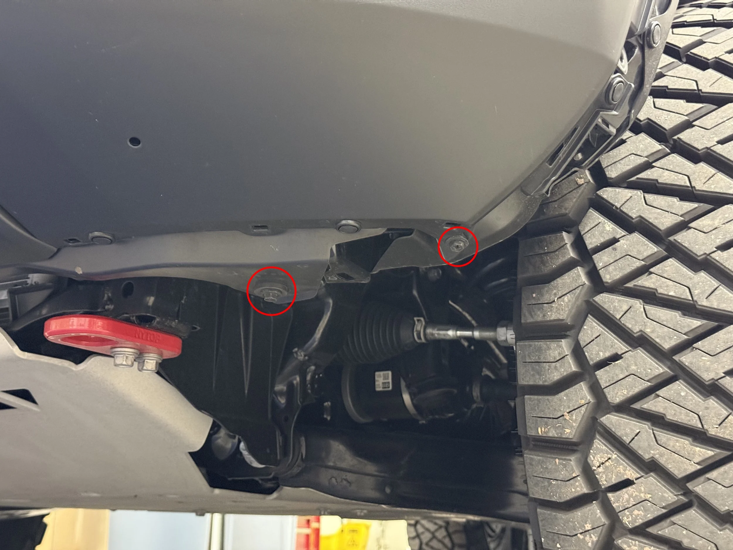
Start by removing the lower air dams on each side of the vehicle by removing the 10mm bolts and the push pin clips as shown in the pictures.

Under vehicle view showing two USB ports circled in red and a red lifting eye bolt with washers.
Under the car, showing a black metal component with a red circle highlighting a screw or bolt.

Remove the air deflector on each side by removing the push pin in the wheel well and the tabs on the bottom (twist to remove).

Underbody view of a truck showing three red circled mounting points or fasteners.

Remove the bumper base cover held on by 10mm bolts and a push pin as shown in the picture.

Close-up of the front left wheel and fender of a blue off-road vehicle with red arrows pointing to various parts of the wheel well, tire, and fender lining.
Black curved plastic piece with multiple screws marked in red, resting on cardboard boxes in a warehouse or store setting.

Remove the front fender flares by first removing the push pins and 10 mm bolts as indicated in the pictures and then pull on the fender flares to release the clips on the back side. Remove any mud flaps first if equipped.

Close-up view of the front right wheel well of a vehicle, showing part of the tire with an aggressive tread pattern and a portion of the fender. The image highlights several screws and fasteners near the wheel arch, some circled in red, with the vehicle's body panel partially removed or disassembled.
Close-up view of the underside of a vehicle, showing part of the wheel and tire, with two bolts circled in red, and area of the chassis assembly.

Remove the push pins and the 10 mm bolts as indicated.

Engine bay of a Toyota vehicle, showing various engine components, hoses, and reservoirs. The engine cover is labeled with oil information, and seven bolts circled in red are highlighted around the cover.
Close-up of two textured metallic screws or bolts resting on a dark grey metallic surface.

Remove 8 push pins holding the radiator support cover, and remove the cover.

To release the push pin, simply push down on it (like the one on the left in the picture). You will need to push the tab back up before reinstalling the push pin later (shown on the right).

Close-up of a vehicle's engine bay with three bolts circled in red, indicating the mounting points for the front grille or radiator cover.
Underneath view of a vehicle showing parts of the suspension, skid plate, and wheel with a warehouse background.

Remove three 10 mm bolts on top of the grille and two 10 mm bolts on the bottom of the bumper.

Under the hood of a car, close-up view of electrical components and wiring, with a red arrow pointing at a specific connector or component.
Close-up view of an automotive electrical connector with multiple colored wires, attached inside a vehicle's dashboard or control panel.

Disconnect one plug on each side of the bumper behind the wheel liner. Make sure to lift the lever on the passenger side (left hand drive) plug first before disconnecting.

Close-up diagram of a blue electronic device with a labeled inset showing removal or attachment of a component with an arrow.
Diagram showing a blue electronic device with a close-up of a latch and an arrow pointing to it, indicating how to open or operate the latch.

Release the bumper tabs by pulling towards the indicated direction. Remove the bumper cover.

Disassembled electronic device or appliance with visible internal components, placed on a blue padded mat on a concrete floor, with four screws marked with red circles.
Disassembled car dashboard with four screws circled in red for removal or assembly.

Remove the lower valance from the bumper. It is held on by 4 push pin clips on the bottom, two phillips screws and two white nylon clips on the back side.

Close-up of a mechanical part with a large bolt, a washer, and a rubber bumper or pad, all assembled on metallic surfaces, with a red circle highlighting the rubber bumper.
Front of a vehicle with the front bumper removed, revealing internal components, with two red arrows pointing to specific parts of the vehicle's frame or radiator area.
Close-up of a black mechanical component with a small slot or opening, outlined by a red circle, showing metal parts inside.
Person using a screwdriver to tighten or loosen a small screw on a metallic surface, possibly part of a machine or device.

Remove the plastic crash bar cover held on by clips as indicated.

Close-up of a car's radiator mounted with two bolts circled in red.
Close-up of a car engine with four bolts circled in red.

Remove four M12 bolts and two M10 bolts on one side of the crash bar, while keeping the other side intact to prevent movement of the crash bar.

Close-up of a car chassis with a red mounting bracket and a jack underneath, supporting the vehicle in a garage or workshop.
Front view of a partially disassembled vehicle with its grille and bumper removed, exposing the radiator, cooling fans, and various internal components, on a workshop floor with tools and pallets in the background.

Install the recovery point by first hand tightening all the bolts. Add a supplied washer on each of the upper bolts only. Then tighten the lower 4 bolts, while leaving the upper bolts loose. Repeat on the other side.

Use a jack if necessary to adjust the angle of the recovery points while tightening the upper bolts, so that the recovery points are perpendicular to the crash bar and level to each other.

Torque down the M10 bolts (the 2 smaller bolts) to 35 ft-lbs./47 Nm, and the M12 bolts (the 4 larger bolts) to 75 ft-lbs./101 Nm.

Front view of a blue Toyota off-road vehicle with the hood open, surrounded by tools on a blue mat in a garage or workshop.

Reinstall the bumper cover by reversing the previous steps. Don’t forget to plug back in the wiring harness on each side.

Close-up of the front lower bumper of a vehicle with four red circles around the mounting holes.
Front view of a blue Toyota off-road vehicle with large tires in a garage.

Slide the NYTOP hybrid bumper onto the recovery points and install 4 of the supplied M12 bolts with washers to secure the bumper to the vehicle.

The height can be adjusted with the supplied square spacer plates if needed. We recommend starting with 2 spacer plates on each side.

Torque down the M12 bolts to 75 ft-lbs./101 Nm. and the installation is complete.

Skip to the next step if you have purchased the Bull Bar along with the bumper.

Close-up of a metallic surface with two holes, part of a larger gray and black object, on a quilted fabric background.
Close-up view of a metal hinge with two silver bolts attached to a dark metal structure, with a quilted fabric surface in the background.

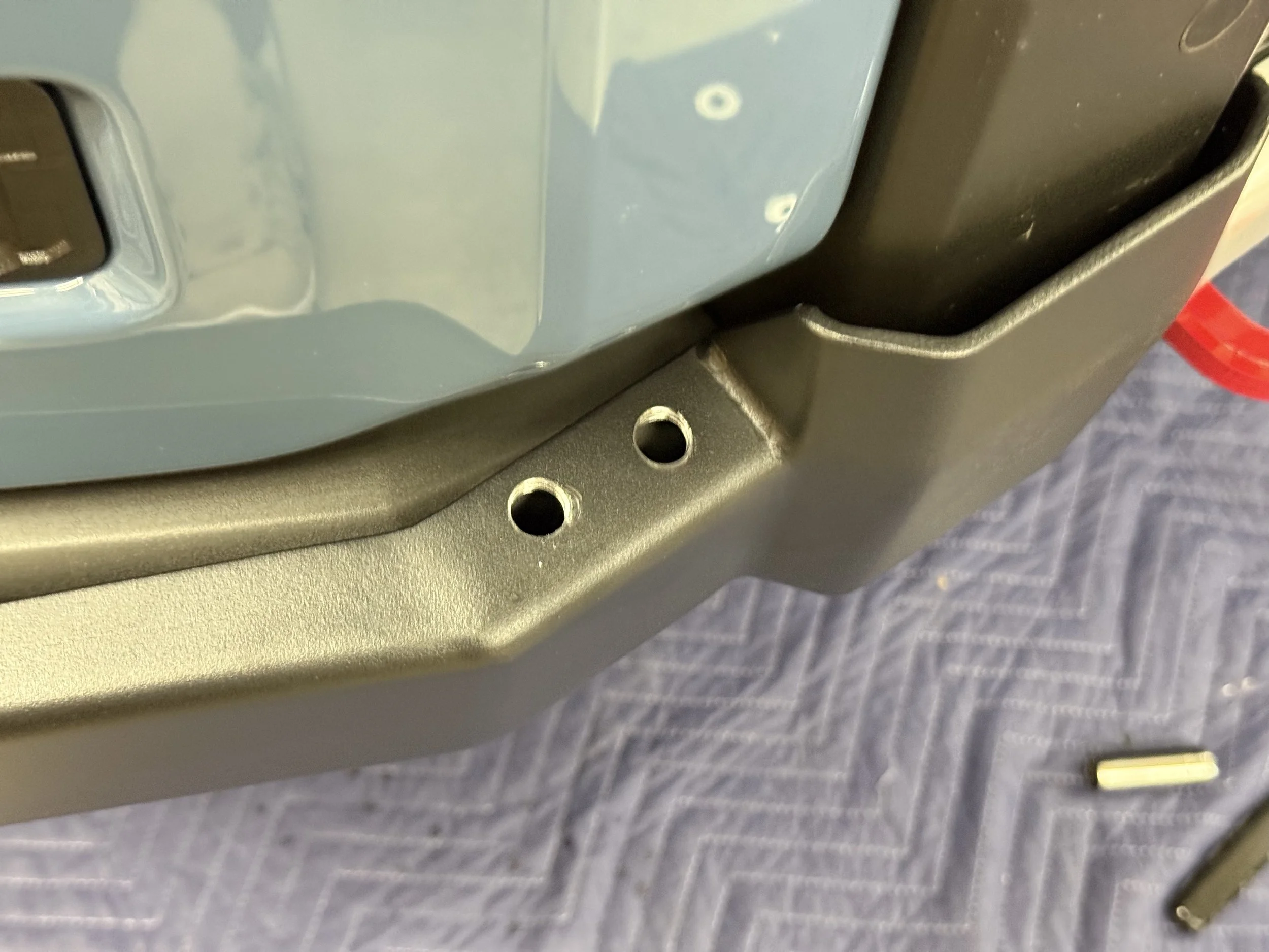
With the bumper off the vehicle, line up the bull bar onto the bumper, and mark two holes on each side of the bumper. Drill 4 holes with a 10.8mm drill bit or equivalent, and tap the holes with a M12x1.25 (fine metric threads) tap.

Install the bull bar with the supplied M12x1.25 bolts with a washer on each bolt.

Front view of a blue Toyota off-road vehicle parked on asphalt showing large tires and rugged design.

Install the bumper and bull bar assembly following the previous steps.

Enjoy the Recovery Points and the added protection!

Not Your Typical Off-road Parts